|
This is a summary of a "Powerpoint" presentation given by Dr. Martin Gale to The Telford Polymer Association on 19 January 2005 |
|
Development
of the Minimixer
|
|
Dr.
Martin Gale
|
|
Telford
Polymer Association
|
|
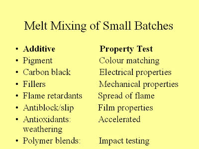
1.
Introduction (Slide 1) Many polymer laboratories both in industry and academia need to compound very small quantities of plastics materials to incorporate additives. Whilst factory production and pilot scale facilities can use twin screw compounding extruders and internal mixers, laboratory work is often hampered by either the unavailability of small compounding equipment or the limitations of existing machines. To meet this requirement, the author developed a small batch mixer to compound about 20g of material in a convenient form for evaluation by standard methods. A prototype made by Jones Engineering Services (Shrewsbury) became the subject of a research project at Bradford University with 3 sponsoring plastics companies and supported by EPSRC. (grantGR/S14337/01). The machine was designed to have both the mixing performance and versatility of a typical twin screw compounding extruder. |
|
Slide 1
|
 |
|
2. Inception
and Design |
|
Slide
2
|
 |
|
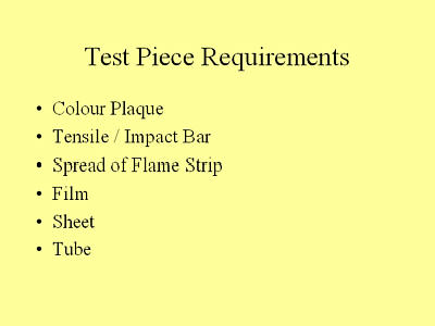
2.2. Test
Piece Requirements (Slide 3) |
|
|
 |
|
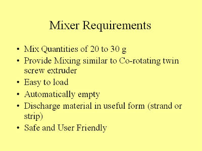
2.3. Mixer
Requirements (Slide 4) |
|
Slide
4
|
 |
|
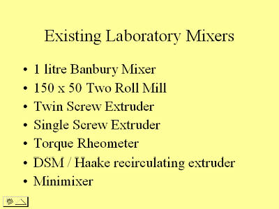
2.4. Existing
Laboratory Mixers (Slide 5) The 1 litre Banbury (or internal) mixer was ideal for rubber mixing but for plastics (in addition to being too big), there were contamination and handling problems of discharged materials. With the 150 x 50mm two roll mill, materials other than rubber or PVC would either not band or conversely stick to the rolls to an extent that removal was difficult. The
twin screw extruder was good in all operating respects but cleaning time
could be extensive and significant quantities of material were required
to establish stable compounding conditions. The machine was also very
expensive. The
Torque Rheometer was a genuine small batch mixer holding about 35g and
would satisfactorily compound many materials although its dispersive mixing
was limited by the non-intermesh of the rotors. The main problem was discharging
the mixed material in a readily usable form. There were also hazards in
handling very hot metal parts and potential exposure to rotating parts
when discharging and cleaning. The author has no experience of the DSM original and derived mixers but they appear to meet more of the requirements in Slide 4 than any described above. Examples are the Thermo-Haake "Minilab" which doubles as a rheometer and has a charge weight of as little as 8g. and the DACA holding 6g. These mixers consist of a conical twin screw extruder with a recirculation channel and a discharge port closed by a valve during mixing. Lastly
we have the Minimixer, which is described, in the following sections. |
|
Slide
5
|
 |
|
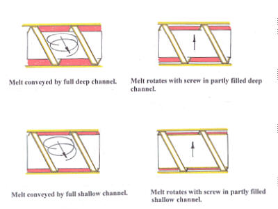
Single screw extruders have a poor dispersive mixing performance. In single screw extrusion of finished products such as polyethylene pipes, good dispersion has already been achieved by the colour masterbatch supplier, whilst good colour/masterbatch distribution can be achieved by fitting a peg mixer, Cavity Transfer Mixer etc., depending on distributive mixing performance required. In the case of the Minimixer, by duplicating the mixing elements of a twin screw compounding extruder the dispersive mixing of such a machine can be reproduced. The addition of an interacting in-line screw ensures there is good distributive mixing. |
|
Slide
6
|
 |
|
|
|
Slide
10
|
 |
|
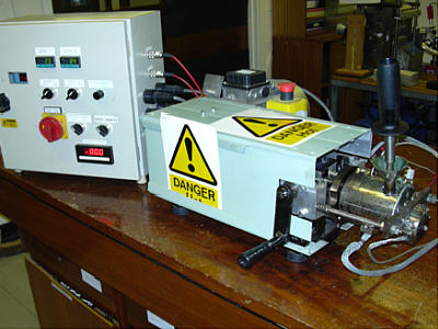
For safety, opening and closing is by rack and pinion arrangement operated by turning a handle which opens by moving the barrel and die away from the mixing elements and screw. As an additional safety feature the opening head opens a microswitch, which prevents the drive working. An emergency stop button is also fitted. |
|
Slide
19
|
 |
|
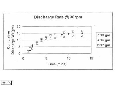
The strand can then be granulated and moulded or extruded for evaluation: diluted if required (as a masterbatch) with natural polymer. The splitter gearbox gives rotor speeds of approximately 3 times the screw speed and being nearly double the diameter of the screw, the rotors impose much higher shear rates than the screw. The speed indicated on the slide is that of the screw. Using LDPE, total discharge time and cumulative discharge time were measured for 3 charge weights. |
|
|
|
Slide
24-25
|
|
 |
 |
|
|
|
Slide
26
|
Slide 30 |
 |
 |
|
|
|
Slide
31
|
Slide 32 |
 |
 |
|
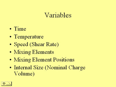
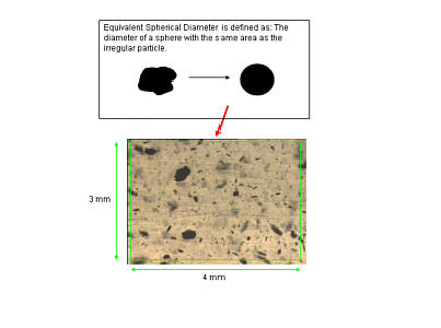
Approximate electrical resistance values were determined immediately by measurements with an electrometer between 2 probes pushed into the strand a measured distance apart. A PTC (positive temperature coefficient) effect was noted as the strand cooled. 3.4.
Influence of Mixing Variables on Particle Size Distribution. (Slides
33 to 36) Samples
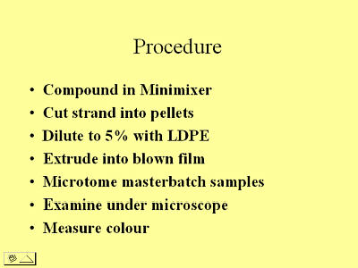
were prepared as follows: - Slide
34 shows batch-to-batch variations for the 3 batches mixed for 8 minutes
at 50 rpm and 8 minutes at 40 rpm. The 40-rpm bar chart is a typical result
and is very consistent. The 50-rpm result is possibly the most variable
so far, but even this can be regarded as reasonably good. A feature of
all the charts is that their shapes are all the same with a peak always
occurring at 0.020mm. |
|
Slide
33
|
Slide 34 |
 |
 |
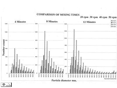
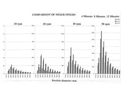
| Slides
35 & 36 use the same data; 35 showing effect of time and 36 that of
speed. As might be expected, increasing time and increasing speed both increase
the number of small particles. It should be noted that to get the graphs
on the same slide, the scales for the 3rd bar chart have been changed (1200
to1400) and hence the influence of 12 minutes is greater when referring
to the values. A similar situation exists for the 4th bar chart in slide
36. From a practical aspect there appears more to be gained by increasing
speed than increasing time. With the Minimixer being a new machine, speed
has been treated with caution, but with experience, maximum speed will probably
be increased by changing the gearbox. |
|
Slide
35
|
Slide 36 |
 |
 |
|
4.
Conclusions So far only the original barrel and mixing elements have been used, but completed work indicates that its volume could be increased, or more likely, decreased to accept smaller, more economic, batch sizes with very costly nano additives. Mixing has proved to be good: so good that it has proved difficult to find differences sufficiently significant to evaluate mixing variables with "normal" materials / formulations. 5.
Acknowledgments |